Emlid Reach Guide #2 – Walkthrough for Base/Rover setup and ReachView-based survey using a known base station coordinate
Author: Chad Hill
Revision date: December 2017
An Emlid Reach RS
The Emlid Reach RS is a low-cost single frequency GNSS RTK (Real Time Kinematic) instrument. It can be used to record approximately cm-accurate points in a variety of workflows. With two Emlid Reach RS instruments acting as a base and rover, you can perform rapid 1-person surveys with a high degree of accuracy.
In this guide, you will be setting up the base station over a point with a with a known coordinate. This would be the situation if you have previously established a base station coordinate using the Emlid Reach RS in static mode (see other guides), you have performed a static survey with some other device (for instance an iGage IG3s dual frequency static receiver and the online OPUS service), or you are using a previously surveyed mark with published coordinates. Either way, you must have coordinates in decimal degrees in WGS84 Latitude, Longitude and ellipsoid height, or in meters in Earth Centered Earth Fixed (ECEF) XYZ coordinates. If you do NOT have a point with known coordinates to set the base station over, you may still do a “relative” survey, where the base station can use “averaging” to get an estimated position. In this scenario, all points recorded with the rover will be up to 1-2cm accurate relative to each other and the base station, but the entire survey data-set will have a high degree of inaccuracy (up to several meters). However, this may necessary depending on field conditions and hardware availability, and may be acceptable for many archaeological purposes.
This guide uses the simplest (and cheapest) survey data recording method available for the Reach RS: onboard survey recording using the “ReachView” app via an iOS or Android device. Using the built-in survey tool is quick, easy to set up, and can work with the widest range of devices. However, there are some important drawbacks to the built-in survey program. Most importantly, you can only record points in WGS84 geographic coordinates. You cannot view or store points in real time in a projected coordinate system such as UTM (Universal Transverse Mercator) or SPC (State Plane Coordinate), which might be necessary for some archaeological applications. In those cases, you will need to use 3rd party survey recording software or a dedicated data-logger (see additional guides).
Walkthrough Overview:
I.
Before
Fieldwork – Required equipment and charging
II.
In the
Field
A. Setting up the Base station:
1. Physically setting up the base
2. Logging into the base via Wi-Fi and the
onboard hotspot
3. Initial base station settings configuration
and base station coordinate entry
B. Setting up the Rover:
1. Physical setup
2. Logging in to the rover
3. Initial rover configuration
4. Setting up and recording points using the
“Survey” tab in ReachView
III.
Troubleshooting
I.
Before
Fieldwork:
The hardware that will be required for field operation of the Emlid RS system includes:
1. 2x Reach RS units
2. 1x GPS survey pole
3. 1x Survey Tripod w/optical plummet Tribrach
4. An Android or Windows Tablet for Data logging and setup
Before going to the field, ensure both reach units and tablet are charged. The reach is charged via a micro USB port on the front of the unit. There should also be a micro USB cable in the Emlid case. The Emlid should charge after a few hours plugged into any USB port. The internal battery will power the Reach RS for many (up to 30) hours of continuous operation.
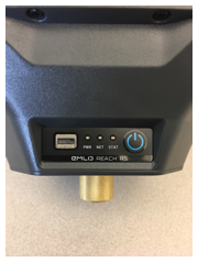
Front panel of the Reach RS, USB charge port at left, 3 status LEDs in the middle, power button on the right. Below is the brass survey tripod adaptor.
II.
In
the Field:
In order to begin using the Reach RS in base/rover mode, you will need to initialize the base over your known point and ensure that it is broadcasting correction data via it’s onboard LoRa radio.
A. Setting up the base:
1. The first step is to physically set up the base station. The base station will send correction data in real time over a radio link to the second unit acting as a Rover and recording coordinates for unknown points. To begin, place the survey tripod, with the tribrach, over the point that will act as the base station location (alternatively, you can use a GPS survey pole with a bi-pod or tripod and a spirit level to place the receiver over your known point).
Mount the Reach RS base station to the tribrach using the brass adaptor, and ensure that the reach is level and directly over the survey mark using the leveling screws and optical plummet of the tribrach:
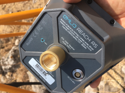
Left: the bottom of the Reach RS, this is the location to measure to when recording HI. Right: Survey tripod with tribrach setup over known survey point (cemented rebar with flagging tape).
Be sure to screw the external radio antenna into the bottom of the Reach RS before turning the device on! Measure the distance (in meters) from the survey mark to the base of the receiver using a hand tape. Add 6.5mm to this measurement to get the height of the instrument (HI). Note this measurement, we will need to enter it below.
2.
All setup of the Reach RS is accomplished via a
Wi-Fi connection and through a browser window or the “ReachView” App for iOS
and Android. The Reach RS can either connect to a Wi-Fi hotspot or generate its
own Wi-Fi hotspot. The “ReachView” app can be downloaded here for iOS:
https://itunes.apple.com/us/app/reachview/id1295196887?mt=8
Or here for Android:
https://play.google.com/store/apps/details?id=com.reachview&hl=en
N.B. You will only be able to access your Reach via
the Android and iOS apps if you have already updated your Reach RS to firmware
2.8.0 or higher. Please see the “initial setup” guide for directions on how to
connect the Reach to the internet to update firmware.
For the type of survey described here you do NOT need the base station to access the internet, so you can allow it to generate its own wifi hotspot. If you have previously configured your Reach to utilize the hotspot in your phone, you should turn your phone hotspot off so that the Reach does not log into it. When you turn on the Reach RS, it will first look for Wi-Fi networks it knows, and then create its own hotspot if it finds none. Turn on the Reach by pressing the power button for 3 seconds. The front LED lights should flash. After a few moments, the blue “Net” LED light should come on solidly to indicate the Reach RS has initiated the internal hotspot (if the blue “net” light is blinking, the Reach RS has instead logged on to an external Wi-Fi network). On your mobile device, search for available Wi-Fi networks and look for the one that is called either “reach:xx:xx” or, if you have renamed your Reach during the initial setup, it should have that name plus “:xx:xx”. In the example below, the Reach network is available as “DartmouthBase:f7:a5”. Log on to that network using the password “emlidreach” unless you previously selected a more secure password.
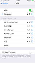
An iPhone Wi-Fi network selection window, showing “DartmouthBase:f7:a5” as an available network
Once connected to the Reach hotspot, open the “ReachView” app. You should be presented with a screen showing all available Reach units. Since you are connected to a Reach-generated hotspot, the list should only include the one Reach you are connected to:
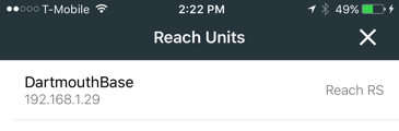
Select this Reach and, after a loading screen, you will arrive at the main ReachView status page for this unit:
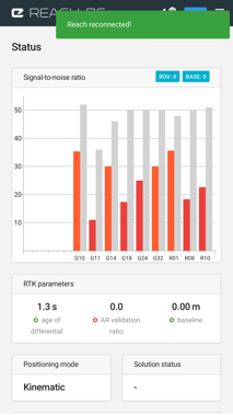
The main status page for the Reach RS
Alternatively, any time you are connected to the internal hotspot in your reach, you can always access the same status page (and all additional ReachView pages) via a web browser by entering 192.168.42.1 in the address bar.
3.
There are many pages of settings accessible via
the “navigation pane” in ReachView. On a larger tablet or laptop computer, the
navigation pane is always visible on the left side of the screen. On a phone or
small tablet in the Reach View app, the navigation pane is accessed by tapping
on the ![]() icon. Below is a brief overview of the
important settings for base station operation. While this is a long list of
settings, after the base station is set up for the first time, you will NOT
need to access most of these pages. Once you have setup the base station
successfully you will ONLY need to change settings in the “Base Mode” page, and
then only if you change the location of the base station or change the height
of the base station over the same point because you have broken it down and set
it up again.
icon. Below is a brief overview of the
important settings for base station operation. While this is a long list of
settings, after the base station is set up for the first time, you will NOT
need to access most of these pages. Once you have setup the base station
successfully you will ONLY need to change settings in the “Base Mode” page, and
then only if you change the location of the base station or change the height
of the base station over the same point because you have broken it down and set
it up again.
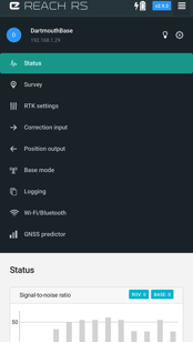
ReachView navigation pane
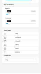
RTK Settings: Below are some initial recommended settings for the “RTK Settings” page. These might need to be changed depending on where you are using the Reach RS or if you are having problems getting a fix. Please see additional note about troubleshooting below.
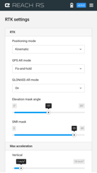
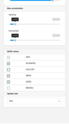
Recommended initial “RTK settings”
Correction input: Since we are not receiving any corrections TO the base, you should ensure that “Base Correction” and “Additional Correction” are both switched “off” in the “Correction Input” screen.
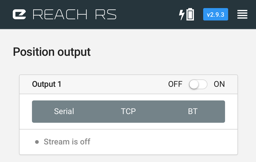
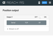
Position output: The base station is not sending a position output to any external device (like a datalogger). This is different than the correction data that it will be sending via the “base mode” page. You should ensure that the “output 1” is turned off in the “Position Output” page:
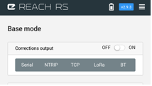
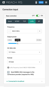
Base mode: The “Base Mode” page is where the main changes need to be made in order to setup the base to broadcast correction data to the rover.
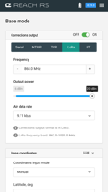
Ensure that “Corrections output” is turned on. You have 5 options for correction output listed at the top: Serial, NTRIP, TCP, LoRa, and Bluetooth (BT). The LoRa radios, are the internal radios included with the Reach RS and are the easiest way to use a pair of Reach RS units in Base/Rover mode. Select the “LoRa” tab. Unless you have problems with interference or loss of signal, leave “Frequency”, “Output Power”, and “Air data rate” at their default settings as shown above.
N.B.
If you will be travelling out of “Line-of-site” of the base station, you should
lower the “speed” of the radio communication. This will improve the range of
the radios. In this case change the “air data rate” to the smallest number that
is not greyed out (likely 2.6 kb/s). You must ensure that you ALSO change the
air data rate to the same value in the rover (see below).
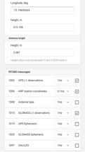
Under “Base coordinates” you should change the “coordinates input mode” to “manual” and then enter the latitude, longitude, and height of your known point in decimal degrees. Add the HI measurement you made earlier under “Antenna height” (i.e. the distance in meters from the known point to the bottom of the Reach RS plus 65mm).
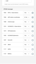
For RTCM messages you should leave just “GPS L1 observations (1hz)” “ARP station coordinates (.1hz)” and “GLONASS L1 observations (1hz)” checked.
Hit apply to save your base station setup in the Reach. The base station will now be broadcasting correction data via the LoRa radio.
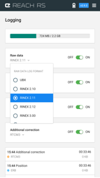
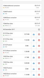
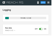
Logging:
If you want to be able to do any post-processing, you should ensure the
base station is logging its raw observation data. Turn “Raw Data” on, and
select the latest Rinex format (3.03) from the dropdown menu. You can download
previous logs by scrolling down and pressing the “![]() ”
icon next to the log you wish to download.
”
icon next to the log you wish to download.
Wi-Fi/Bluetooth: you do not need to change anything in this screen while setting up the base station.
GNSS Predictor: This screen provides helpful information about the availability of different GNSS satellite networks depending on your location and the date/time. This can be useful for planning survey campaigns or identifying problems, but there are no settings to change on this page.
Survey: This is the page for recording survey points. This page will be used when connected to the Rover, but there is no need to access this page when connected to the Base station.
You should now have your Base station set up over a known position and broadcasting correction data to any listening rover. Next we need to setup the rover to receive this information.
B. Setting up the Rover:
Now that the Base station is broadcasting its correction data, you can set up your Rover to receive the correction data and start surveying. The following will walk through the initial setup of the rover. However, once the Reach is working with the base station, you will not need to go through all the settings on every startup. You can just turn on the rover and it will automatically connect to the base station and start trying to establish a “fix” position, assuming you did not make any changes (other than base station position) in the base settings:
1. Mount your other Reach RS on a GPS survey pole, using the brass adaptor. Be sure to attach the included black LoRa antenna on the bottom of the device. Measure the distance from the tip of the survey pole to the base of the RS (the same spot as you measured to on the base station) and add 65mm. Record this information as the Rover HI (Height of Instrument) for use when starting the survey (see below). Turn on the Reach by holding power down for 3 seconds. The lights will come on and blink. After a few moments, the lights will stop blinking and the blue “net” light will turn solid (as above, if the “net” light is blinking, then the Reach has logged into a known network rather than starting the internal hotspot). Look for the Reach-generated Wi-Fi network in your tablet or phone. It should either be the default “reach:xx:xx” or your previously created name plus “:xx:xx”. If you are still within range of the Base station hotspot, be sure to select the correct Wi-Fi network for the rover and not the base. Log on to that network using the same “emlidreach” password (or your previously selected more secure password). Open the ReachView app and select the Reach unit from the list (the same device as the hotspot name). If you were just connected to your base station, you may need to quit and re-launch the ReachView App to refresh it.
2.
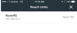
Reach selection screen in “ReachView” app
Once you select your Reach RS in the ReachView app you should see the ReachView loading screen:

Followed by the main “status” screen showing you basic info:
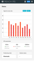
Below the “signal-to-noise ratio”
data (showing the number of satellites currently visible) you will see the “solution
status” box. There are 4 possible things that can show here “-“, “single”, “float”, or “fix”. If “-“
is displayed, it means the Reach RS cannot see enough satellites to establish
an uncorrected position. On the initial power on if you are
outside, but before you have set up the rover to receive data from the base
station, this should say “single” after a short time. Once we set up the rover
to receive base station corrections, this will change to “Float” and then, when
a precise position has been calculated, it will change to the status we need:
“Fix”.
3.
As with the base station, there are many pages
of settings that can be changed before using the Rover. Below is a walkthrough
of the important settings on most of these pages. Different pages are accessed
by pressing the ![]() icon at the top of the screen:
icon at the top of the screen:
RTK settings: As with the base, these are the recommended initial settings. These might need to change depending on where you are having problems getting a fix. Please see additional note about troubleshooting below.
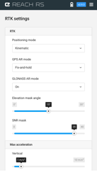
Recommended initial RTK settings
Position output: There are many ways to record position data using the Rover. You can connect the rover to a traditional data logger and record points using specialized survey software, you can output location data to an android tablet using Bluetooth and record points in one of several 3rd party survey apps, you can even connect to a windows computer or tablet using Bluetooth or a USB cable and record points directly in a GIS software package (like ArcGIS or QGIS) or 3rd party data logger software (like SurvPC). In those cases, you would turn on Bluetooth or serial output on this page. However, the simplest way to record data is by using the onboard survey tool built into the Reach RS and accessed in ReachView via the app or a browser. Since that is the workflow being described in this walkthrough, you should turn off “position output”.
Base mode: Since this is the rover, and it is not acting as a base station, you should ensure that “correction output” is off.
Logging:
while not necessary for recording points using the onboard “survey” tab,
you might find it helpful to post-process your survey data after the fact. In
this case, it is useful to ensure that “raw data” logging is “on” and the latest
Rinex format is selected (Rinex 3.03). As with the base station logging,
previous logs can be downloaded from this page by scrolling down and pressing
the![]() icon
for the appropriate log.
icon
for the appropriate log.
Wi-Fi/Bluetooth: you should not need to change anything on this page if your firmware is up to date and your Reach is successfully activating the internal hotspot.
GNSS predictor: This page can provide helpful information, but does not contain any settings.
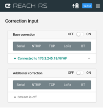
Correction input: Here is where we tell the Rover to receive data from the Base station using the internal radio. On this page, you should turn “base correction” on and then select the “LoRa” tab:
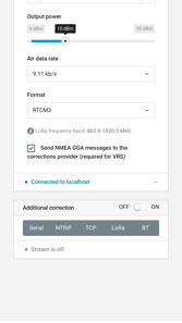
The frequency, air data rate, and format must match the base mode settings on the base station. This should be left as the default settings initially (as above), unless there are interference problems. Once you apply these settings, if the base station is on and broadcasting corrections, you should see a green message at the bottom saying “connected to localhost”. This indicates that the Rover is now successfully receiving data from the base.
N.B. IF You changed the air data rate on the base station, you must
also change it here, or the Rover will not be able to interpret the data it is
receiving. Though you still might, initially, see “connected to localhost” in
green, it will probably change to a yellow “connection timeout” and you will
not be receiving correction data.
Leave additional corrections” off.
Status Screen: Once you have successfully setup all the above settings, and are receiving data from the base station, you should see a second set of “bars” in the “signal-to-noise ratio” window on the main “status” page. Alongside the “orange” value for each satellite being received by the rover, you should see a “grey” value for the same satellite being received by the base.
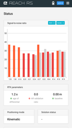
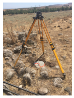
Under “solution status” You are likely to now see “Float”. This means that although it is getting correction data from the base, the rover has not yet figured out how to resolve the complex problem that lets it calculate a precise “Fix” 3D position. Float solutions can be wildly wrong (potentially worse than uncorrected data). You should not start surveying until the solution status changes from “FLOAT” to “Fix”. Depending on several factors, this can take from a few seconds to many minutes. Hold the rover still and at least a few meters from the base station.
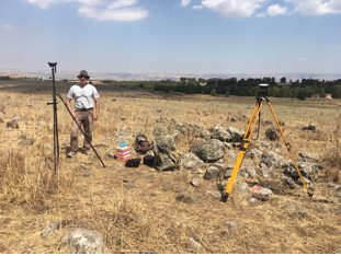
Base and rover setup, waiting for “Fix” status (photo courtesy of the Galilee Prehistory Project)
The solution status should change from Float to Fix after less than 15 minutes. Once the solution status changes to Fix, wait a little longer to make sure the solution is stable. The status may fluctuate rapidly between fix and float for a few more minutes. Eventually it should stay fixed and the AR validation ratio (displayed just below the graph with the green and red bars at the top) should start to climb from 1-2 (when it is Float) to greater (and probably much greater) than 3. Once the solution status changes and stays on “Fix”, you are ready to begin recording points. If you are not getting “fix” status, see troubleshooting below.
4. Recording points:
Once you are receiving corrections from the base station and have a “Fix” solution in the status page, you can begin collecting data on the “Survey” page in the ReachView app. The main “survey” page shows you a list of existing survey projects stored in the internal memory of the Reach and allows you to define new projects
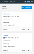
The main “Survey” page in ReachView
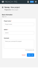
Begin a new project by pressing the
![]() button.
On the following screen, you can enter a name for your project, an author name,
and comments. Enter your information here and press
button.
On the following screen, you can enter a name for your project, an author name,
and comments. Enter your information here and press ![]() .
.
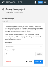
One limitation of recording points
using the onboard survey tool is that you can only record points in WGS84
coordinates. That will be automatically selected on the second settings page,
but you must also enter the Rover HI you recorded earlier under “antenna
height”. Again, this is the distance (in meters) from the tip of your survey
pole to the bottom of the Reach RS plus 65mm. IF you are using a 2m GPS survey
pole AND the brass survey pole adaptor that comes with the Reach RS (which is
21.5mm), then you would enter your antenna height as 2.0865 (2m + 21.5mm +
65mm). Hit ![]() .
.
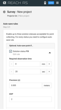
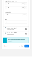
On the 3rd settings
page, you can select “auto-save” rules. These rules allow you to automatically
record a point you collect if the auto-save conditions are met. It is useful
but not necessary to turn on a rule on this page to save a manual step when
recording points in the following screen. In this walkthrough, we will set
auto-save rules for “Fix” only (do not save any points if the solution status
is “float” or “single”). With the settings set as shown below, the Reach will
automatically save a point you collect if, after making observations for 20
seconds, the Dilution of Precision (DOP) is less than 2 and the Root Mean
Square (RMS) error is less than .005m. Depending on the conditions and context
of your survey, you may need to adjust these settings if you find that your
points are rarely or never exceeding these requirements. After entering your
auto save rule hit ![]() again.
again.
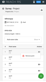
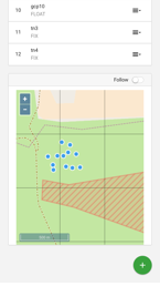
Now you are at the main project overview screen. This page will show you basic info about the project at the top, a list of saved points, and a map of the saved points as well as the current location of the rover and base.
To record a point, press the ![]() button at the bottom of the screen. This will bring you to the “record
point” screen. At the top, you will see basic info about the current state of
the receiver, including “solution” status (fixed, float, single, or “-“), PDOP
(Position Dilution of Precision), # of visible satellites for the base and
rover, Age of differential, Ambiguity Resolution (AR) ratio and the current
baseline length (distance between the rover and base). If you do not have at
least “single” as the solution status, you will not be able to record a point:
there will be a red bar near the bottom of the screen that says “waiting for
solution status” and the “Collect point” button will be greyed out (as in the
image below).
button at the bottom of the screen. This will bring you to the “record
point” screen. At the top, you will see basic info about the current state of
the receiver, including “solution” status (fixed, float, single, or “-“), PDOP
(Position Dilution of Precision), # of visible satellites for the base and
rover, Age of differential, Ambiguity Resolution (AR) ratio and the current
baseline length (distance between the rover and base). If you do not have at
least “single” as the solution status, you will not be able to record a point:
there will be a red bar near the bottom of the screen that says “waiting for
solution status” and the “Collect point” button will be greyed out (as in the
image below).
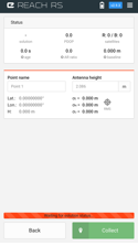
Survey point collection screen, note the receiver currently has “-“ as the solution status. Point collection is not currently available and the warning bar at the bottom says “waiting for solution status”.
Type a name for the point you wish to collect. You may, if needed, adjust the antenna height as well. Do not collect a point unless solution status is “fix”. Once it is, place the GPS survey pole on a point that you want to survey and level the survey pole using the spirit level. While keeping the pole level, press the “collect” button. A timer will count down 20 seconds (based on your auto-save rule), and RMS error values will update constantly alongside the latitude, longitude, and height coordinates. Continue to hold the survey pole level until the timer countdown is complete. Press “Save and Go” to store the point or Cancel to reject it. Move on to the next point you wish to survey and repeat.
Once you are done recording all
your points, return to the main survey project screen and export your points
using the ![]() button. When pressed, you will have the
option of downloading your project as GeoJSON, Esri Shapefile, CSV, or DXF.
button. When pressed, you will have the
option of downloading your project as GeoJSON, Esri Shapefile, CSV, or DXF.
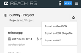
Export dialogue, showing format options
At the end of your survey, press and hold the power button on both the base and rover for 3 seconds to power down the devices and then breakdown the equipment.